Emerging technologies are making our life simpler these days. With the introduction of mobile phones, life has changed rapidly. This is a dream of radio engineering. Mobile phones merged land line telephone systems. These days, many advancements in the mobile phones were introduced. These advancements provide many services such as text, internet etc. But although there are many advancements in the technology, we still rely on the wired battery chargers. Each phone will have its own designed battery charger. Thus the battery chargers are required to carry everywhere to keep the battery backup. Now just think of a battery charger that charges your mobile automatically. When you sit for tea and place your mobile on the table, it simply charges your mobile. This article explains a simple wireless battery charger circuit that charges you mobile when placed near the transmitter. This circuit may be used as wireless power transfer circuit, wireless mobile charger circuit, wireless battery charger circuit, etc.
Wireless Battery Charger Circuit Principle:
This circuit mainly works on the principle of mutual inductance. Power is transferred from transmitter to the receiver wirelessly based on the principle of “mutual induction”.
Inductance is the property of the conductor, in which the current flowing in a conductor induces a voltage or electromotive force in it or in another nearby conductor. There are two types inductance.1)Self inductance, 2)Mutual Inductance.
“Self inductance” is the phenomena in which when the current is passing in one conductor, an emf is introduced in another coil.
“Mutual inductance” is the phenomena in which, when a current carrying conductor is placed near another conductor voltage is induced in that conductor. This is because, as the current is flowing in the conductor, a magnetic flux is induced in it. This induced magnetic flux links with another conductor. Thus this flux induces voltage in the second conductor.
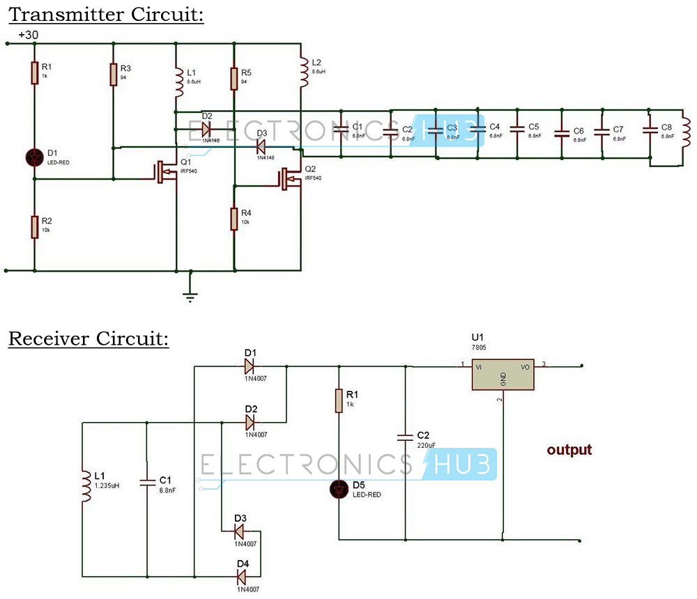
Wireless Power Transfer Circuit Diagram:

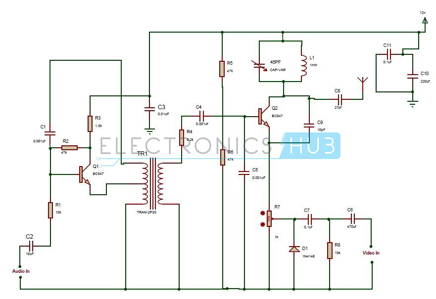
Wireless Mobile Charger Circuit Diagram
Wireless Mobile Charger Circuit Design:
Wireless battery charger circuit design is very simple and easy. These circuits require only resistors, capacitors, diodes, Voltage regulator, copper coils and Transformer.
In our Wireless battery charger, we use two circuits. The first circuit is used to produce voltage wirelessly. Initially, transformer is used to step down the voltage from 230 V to 12V. This step-down voltage is applied to the diode. The 1N4007 diode is used to allow the voltage to flow in one direction only. This is then passed to the 7812 voltage regulator. The output of this regulator is a 12V DC voltage. Two capacitors are placed before and after the voltage regulator to eliminate the ripples. Next it is connected to the oscillator circuit. It produces a frequency of 10 MHz. The values of resistors and capacitors are calculated in such a way that it produces oscillations of 10MHz. Then it is fed to the inductor. Inductor is used to induce the voltage in the second circuit.
In the second circuit, another inductor is used for the mutual inductance. A voltage multiplier circuit is used after the inductor. It is then connected to the voltage regulator 7805.7805 and 7812 are family of 78XX integrated circuit. It produces fixed voltage at the output. 78 represents series and XX represents the output voltage. At the output of the regulator a capacitor is connected. Thus output is connected to the battery.
How to operate this Wireless Power Transfer Circuit?
- Initially, connect the circuit as shown in the circuit diagram.
- Now connect Ac voltage to the transformer.
- Switch on the supply.
- Connect the battery charger at the output of the circuit.
- Make sure that AC and DC sources should not have common connections.
- You can observe the battery charging at the output.
Wireless Battery Charger Circuit Advantages:
- Usage of separate charger is eliminated.
- Phone can be charged anywhere and anytime.
- It does not require wire for charging.
- Easier than plug into power cable.
Wireless Power Transfer Circuit Applications:
- Wireless chargers can be used to charge mobiles, camera batteries, Bluetooth headsets etc.
- This can also be used in applications like car battery charger with little modification. Go to Simple Car Battery Charger Circuit post for more information.
- This can also be used in medical devices.
Limitations of the Circuit:
- Power is somewhat wasted due to mutual induction.
- It will work for very short distances only. If you want to use it for long distances, then the number of inductor turns should be high.